Scanning Hardening of a Splined Shaft
Shafts, steering racks, worm gears and other long or extended mechanical parts are being widely used in automotive, aerospace and many other industries in different mechanical assemblies.
To manufacture these parts, they need to be hardened to improve hardness and wear resistance, and to increase fatigue life. The best way to harden such parts is through induction hardening. It provides selective hardening, which increases system efficiency and decreases the thermal distortions of the part.
In this article we are going to learn how to build a simple splined shaft scanning hardening process using CENOS Induction Heating simulation software.
The setup consists of a 2 winding inductor and low carbon steel AISI 1020 shaft. In simulation 4 kHz frequency and 11 kA current is considered, as well as thermal losses from the shaft.
Download the CAD files used in this tutorial here
1. Prepare your geometry
Geometry is the beginning and a cornerstone of every simulation, so we need to start by preparing our geometry for the simulation.
1.1 Import CAD files
First we need to select the geometry creation approach. In CENOS home window click From CAD.

Click the blinking Folder icon to select the CAD files you want to import.

Select STEP files of your system and click Open to import them into CENOS.
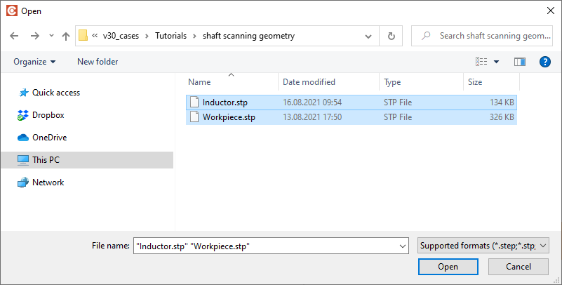
For this example we imported 2 different STEP files - one for the inductor, and the other for the shaft. You can also import both of them in a single STEP file (assembly), it really doesn't make any difference to the simulation!
1.2 Generate air box
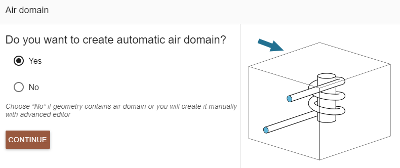
Once the CAD files are uploaded, CENOS will ask if you want to automatically generate the air box (ambient environment around your system). Click Yes on the choice, and then CONTINUE.
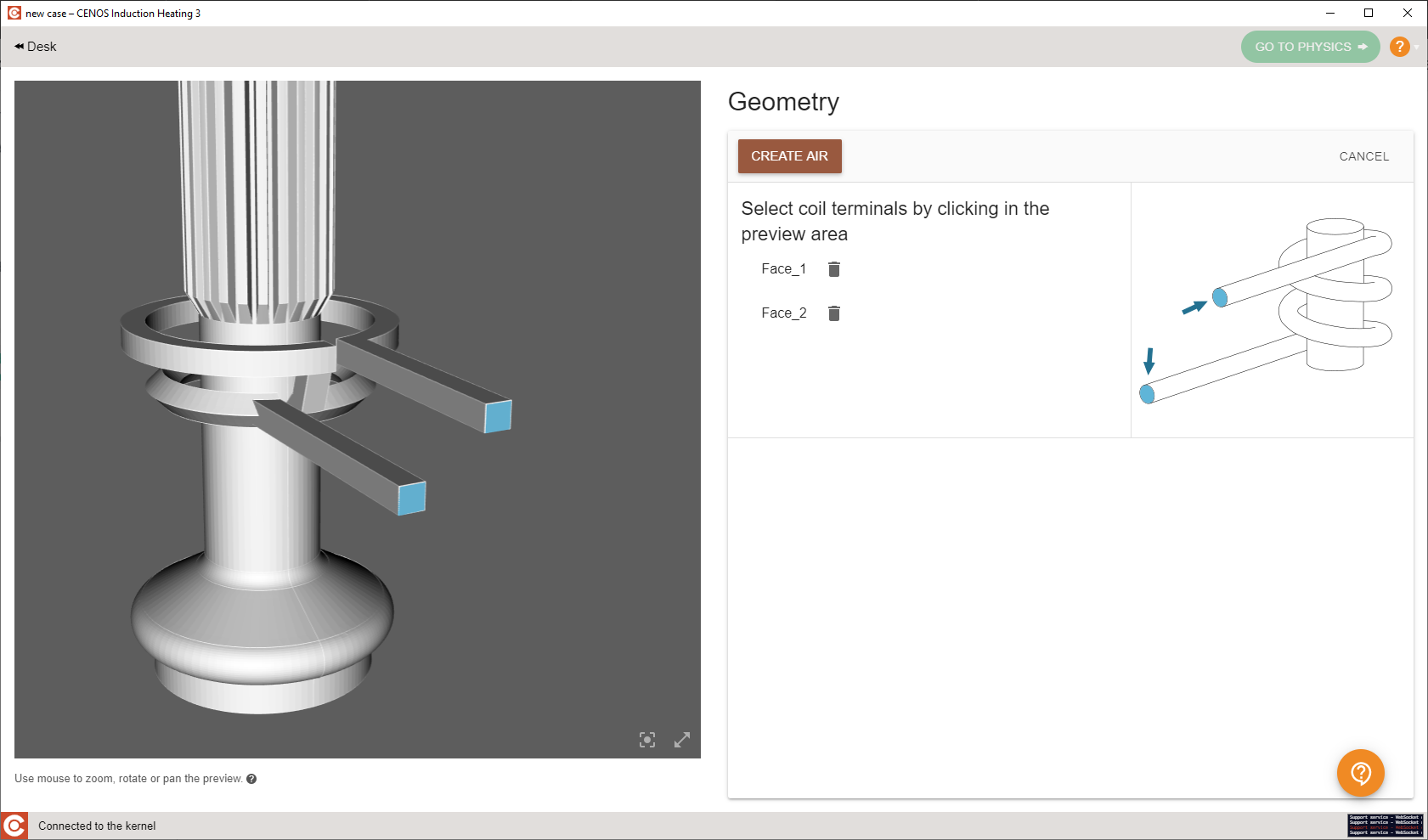
Select your inductor terminals for reference, and click CREATE AIR to automatically generate the air box!
1.3 Define groups
Once the air box is generated, you will be redirected to group creation window. Here you will see a list of groups you need to define for your system, such as which one is workpiece, where are inductor terminals etc.
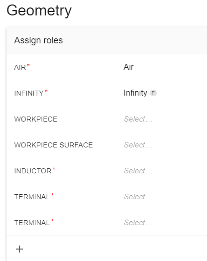
Select the group (in this example, Workpiece), select the corresponding volume from the list or directly from the screen, and click ASSIGN Workpiece.
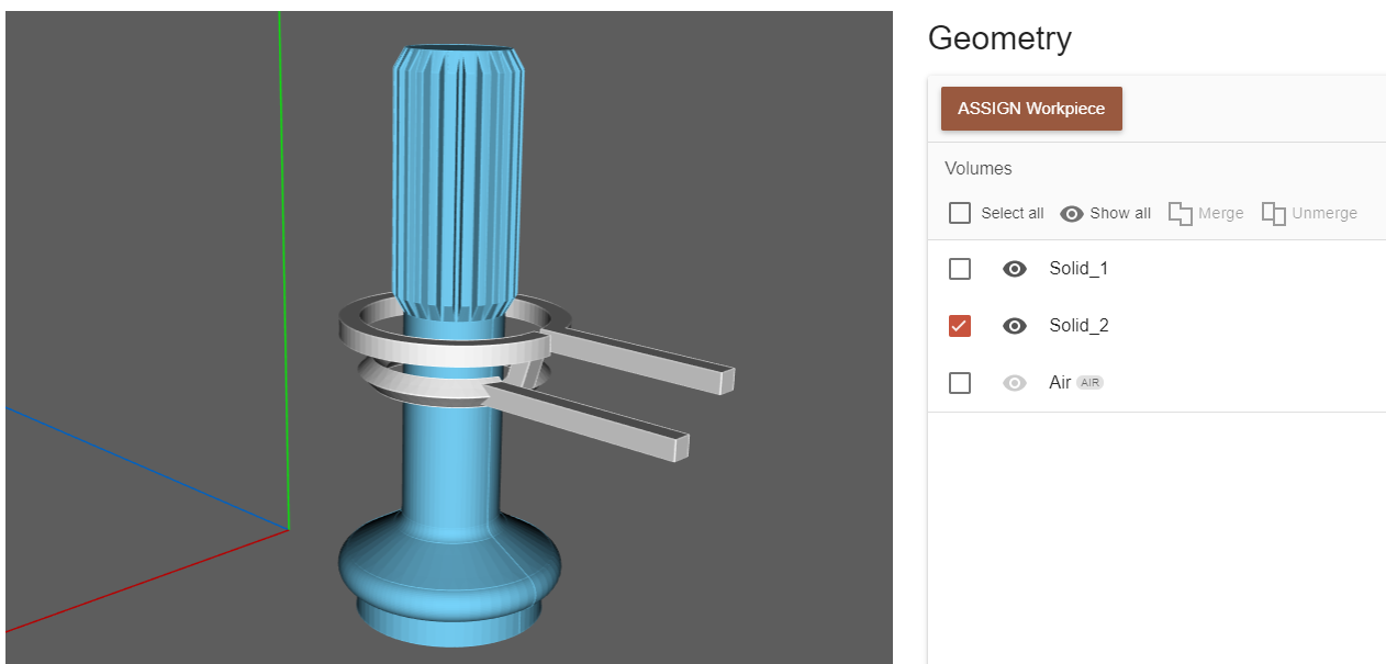
In the same way define the rest of the groups.

You can rename each group by clicking the edit button next to the name!

Once ready, click GO TO PHYSICS for Physics definition!

2. Define physics
You will be redirected to the Physics window, where physical definitions are present. On the left you can see the preview window of your geometry, but on the right - the actual physical definitions. You can navigate physics through the domain tabs above the physical definitions.
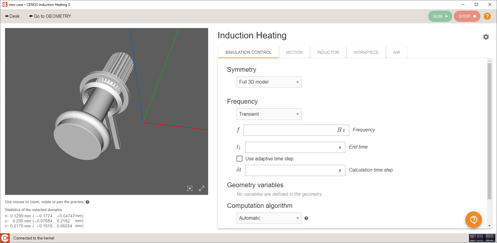
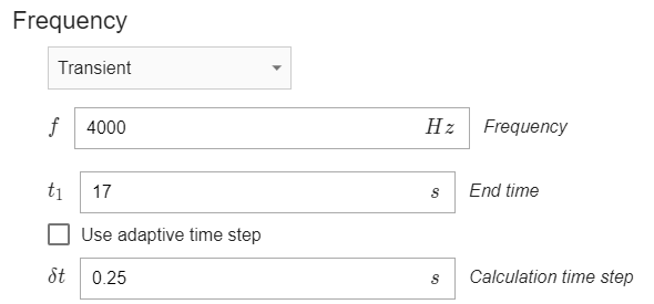
2.1 Simulation control
In the SIMULATION CONTROL window define the simulation as transient with 4 kHz frequency, 17 s End time and 0.25 s time step. For Computation algorithm choose Fast.

2.2 Splined shaft
Select SHAFT from Domain bar. For Material click SELECT… and choose Low carbon steel 1020 (B(H), depend).

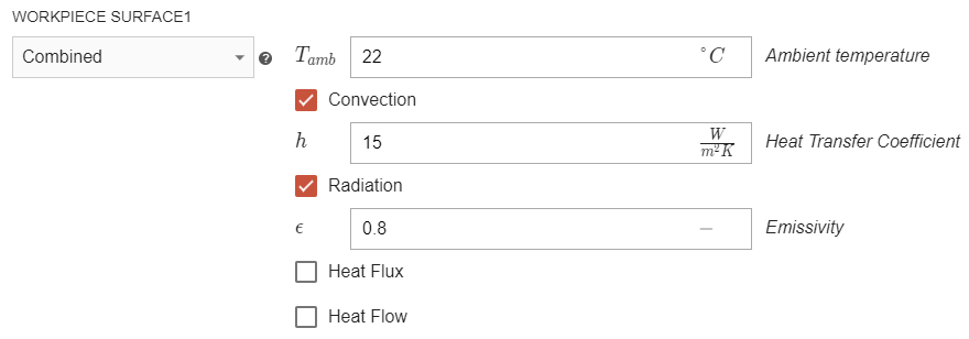
Under THERMAL ANALYSIS for WORKPIECE SURFACE1 choose Combined – check the Convection and Radiation boxes and enter 15 for Convection and 0.8 for Radiation.
2.3 Inductor
Switch to INDUCTOR in Domain bar. For Material choose Copper (Temperature dependent).

Under ELECTROMAGNETICS choose Current (Amplitude) for TERMINAL1, Ground for TERMINAL2 and enter 11000 A as Current (Amplitude).

2.4 Scanning
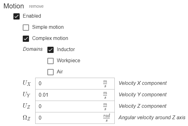
Switch to MOTION tab and click CREATE NEW MOTION.

Check Complex motion as motion type, Inductor as the domain you want to move, and enter movement speed of 0.01 m/s in Y direction.
With the Motion definition you have finished the physics setup! Click RUN to calculate your simulation!
![]()
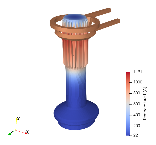
3. Evaluate results
In the end of the calculation our post-processing tool ParaView will automatically open with a pre-set temperature state, and you will be able to see the temperature field distribution in the workpiece in the last time step.
Results can be further manipulated by using ParaView filters - find out more in CENOS result evaluation article.
This concludes our Splined Shaft Scanning Hardening tutorial. For any recommendations or questions contact our support.