Create simulation with From CAD
You can import premade CAD files and prepare geometry for simulation directly into CENOS.
Generate an air box and mesh automatically, and set up the simulation without the need for manual geometry or mesh editing.
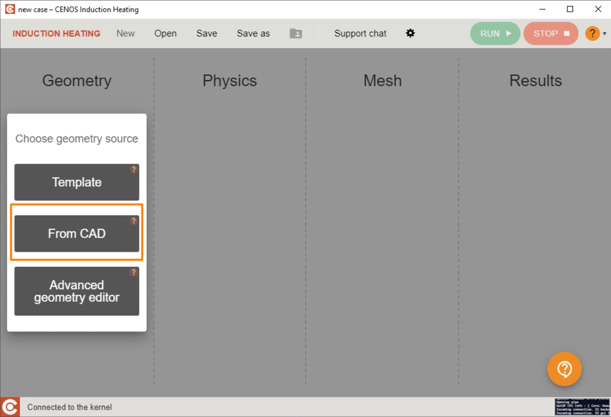
Select the geometry-building approach
To import premade CAD files, click From CAD in the CENOS home window.
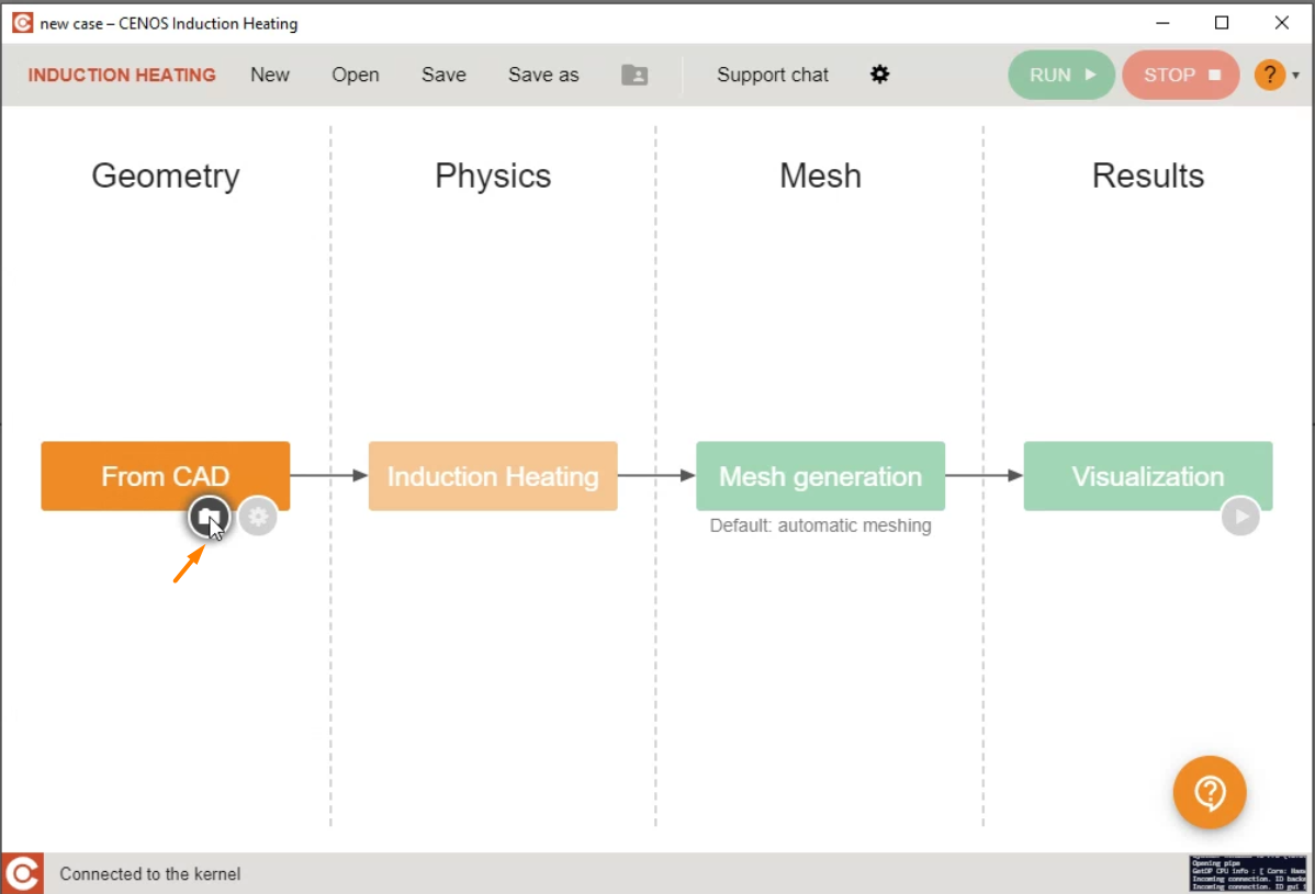
Click on the Folder icon to select and import CAD files.
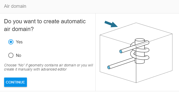
Create an Air Box
Create an air box automatically.
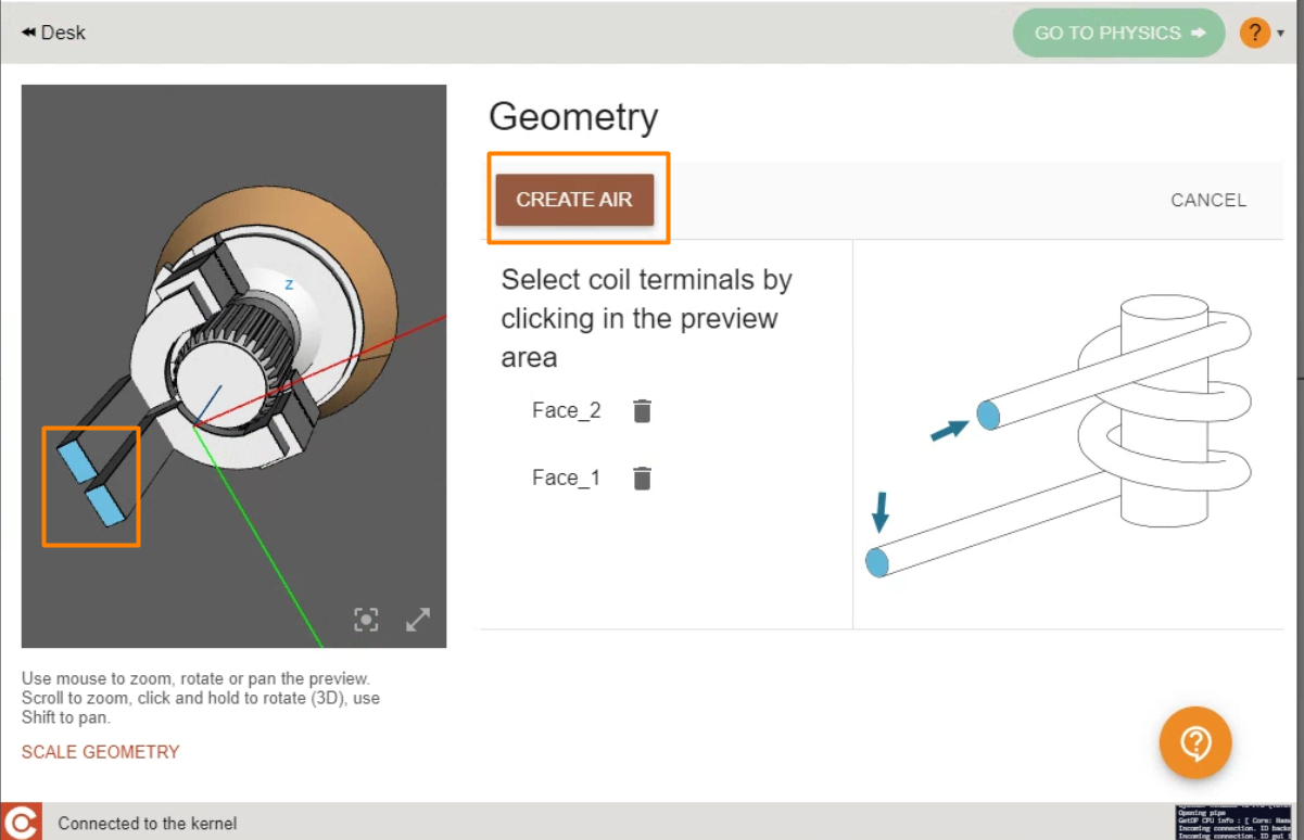
Select the inductor terminals as references for the air box size and click on create air.
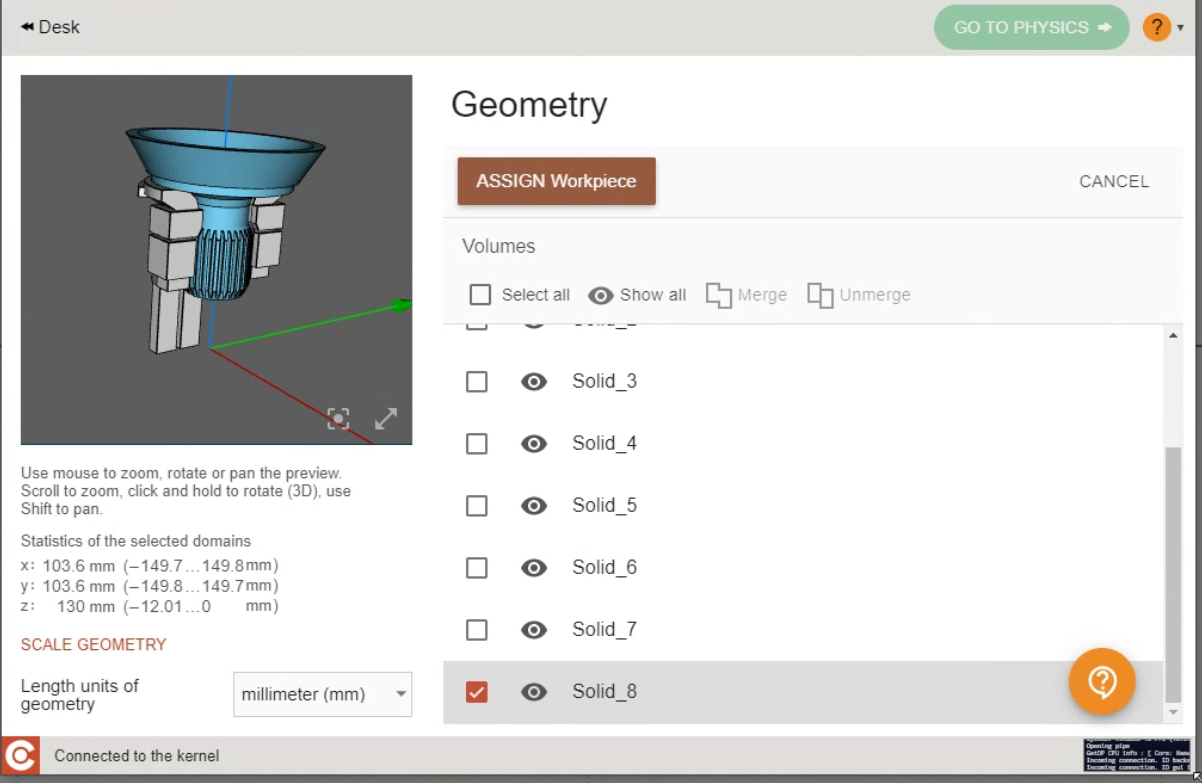
Prepare volumes
IMPORTANT: To make volume and surface selection and preparation easier, the From CAD feature includes multiple useful tools.
![]()
- Select all - Selects all volumes or boundaries available for selection.
- Show all - Turns the object visibility on or off.
- Merge - Merge or group multiple volumes or surfaces into one.
- Unmerge - Split previously merged or grouped objects into their initial state.
Group and rename the volume domains as needed.
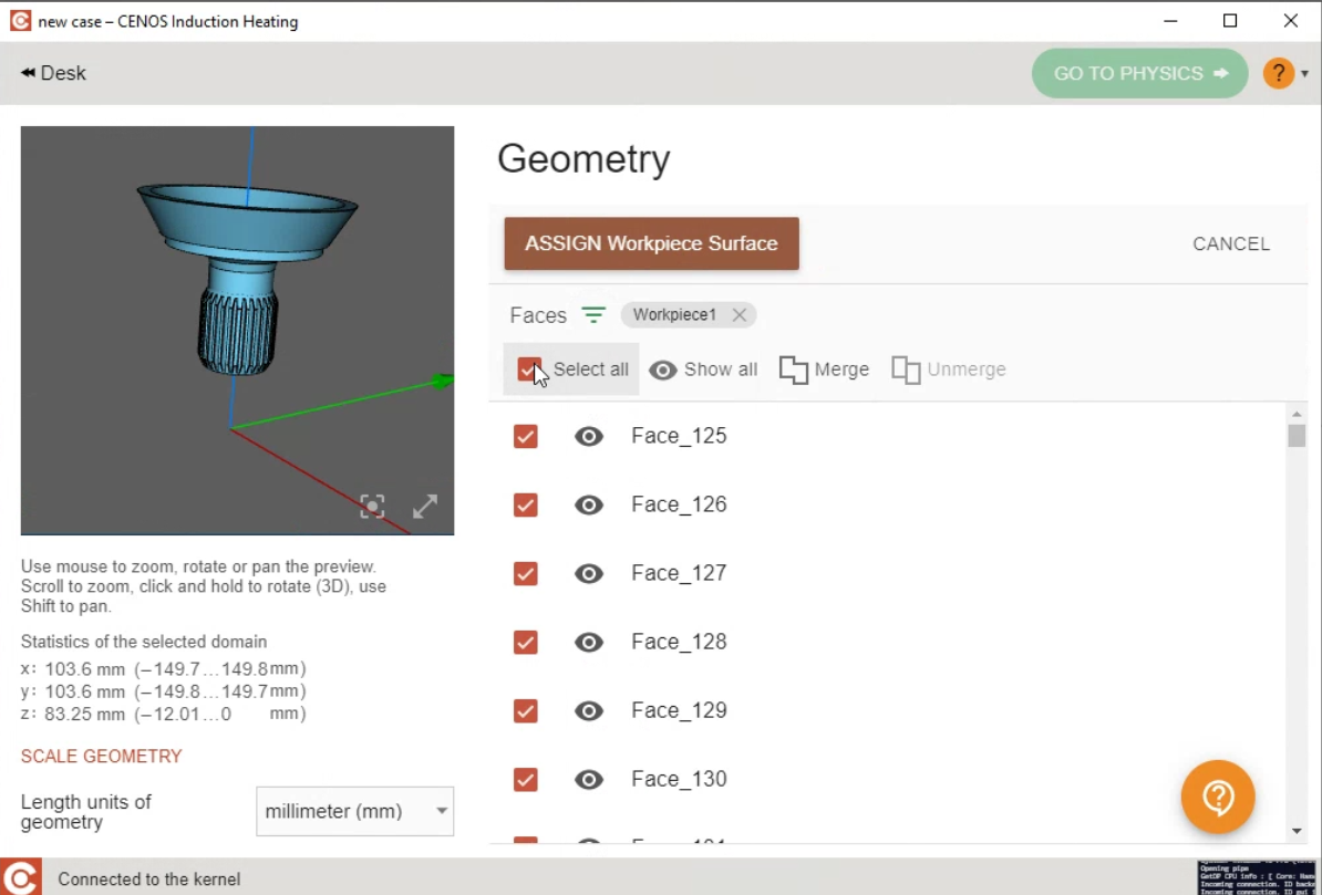
Prepare boundaries
Click on Workpice surface, where you will select the faces that will serve as boundary conditions for the analysis, you can also filter the faces by volume, to make selection easier.
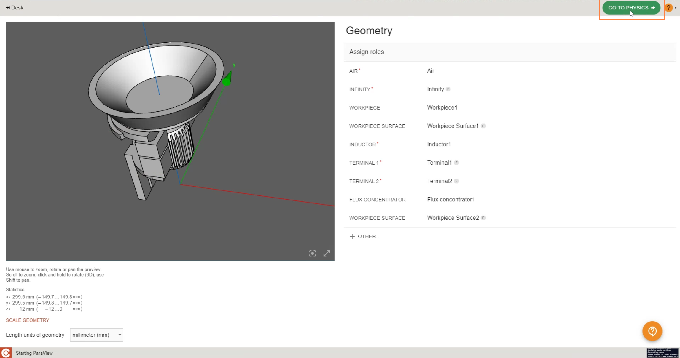
Finally, add as many roles as your system require such as extra workpieces, extra inductors and their terminals, flux concentrators, air and others.
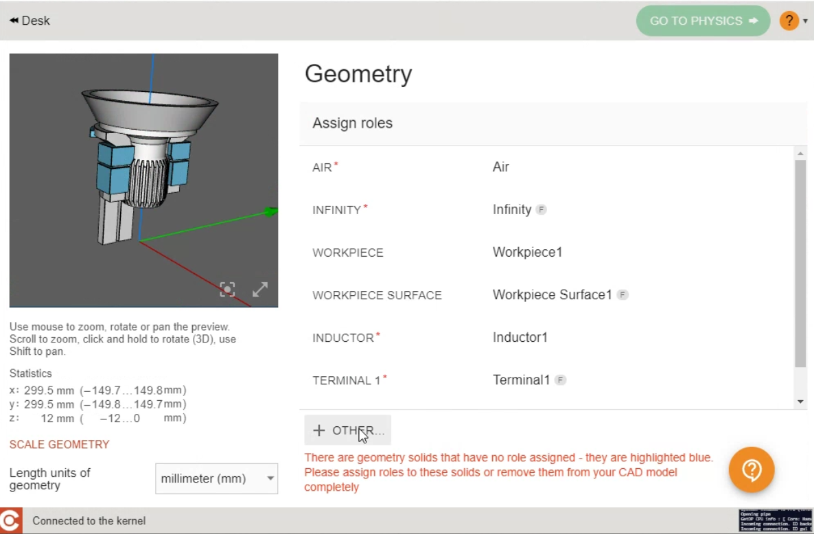
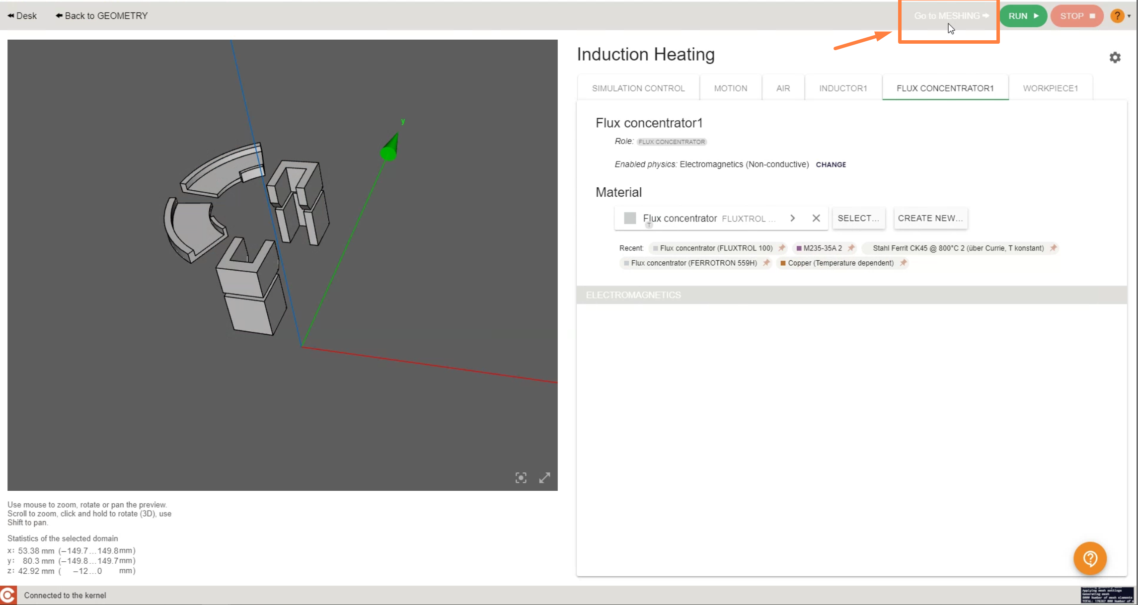
After setting the geometry, click on GO TO PHYSICS to enter physics setup.
Define simulation parameters
Enter physical parameters
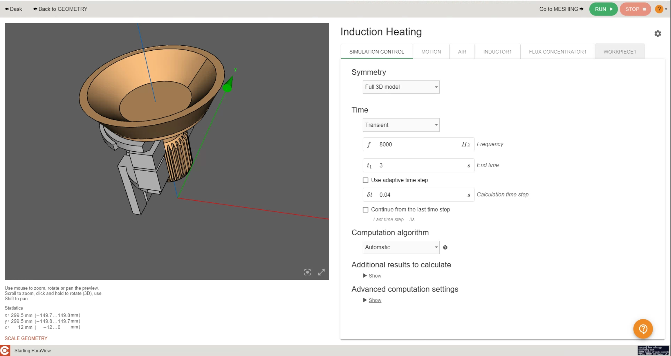
In the SIMULATION CONTROL window define global parameters such as frequency, calculation time etc.
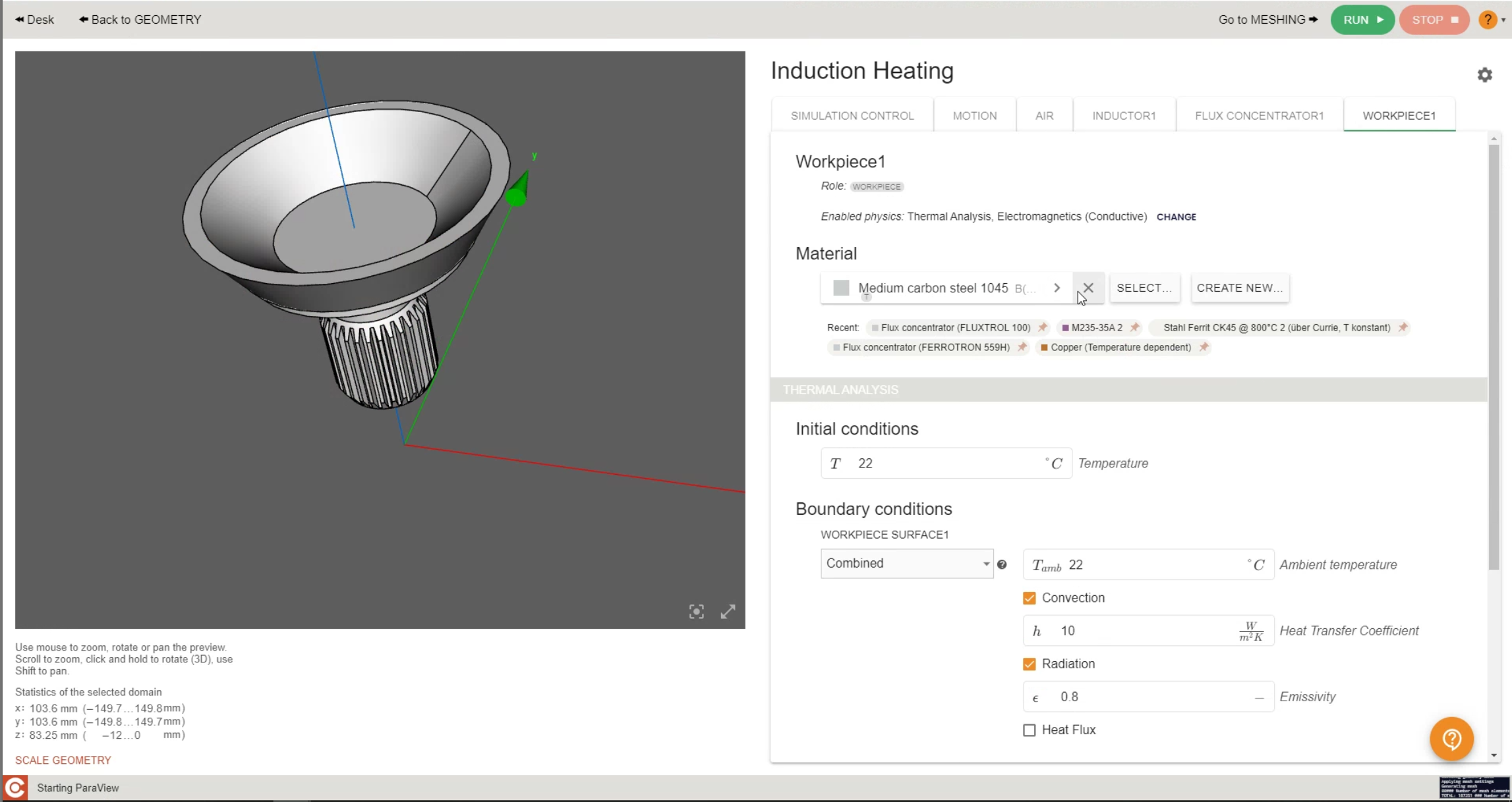
In the SIMULATION DOMAIN windows such as "WORKPIECE" define the physical parameters and boundaries of each domain such as material, heat exchange, current, etc.
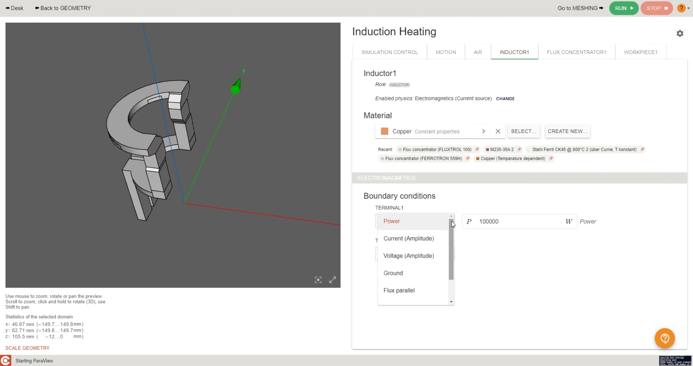
In the inductor section, you will be able to input either voltage, current or power
Meshing
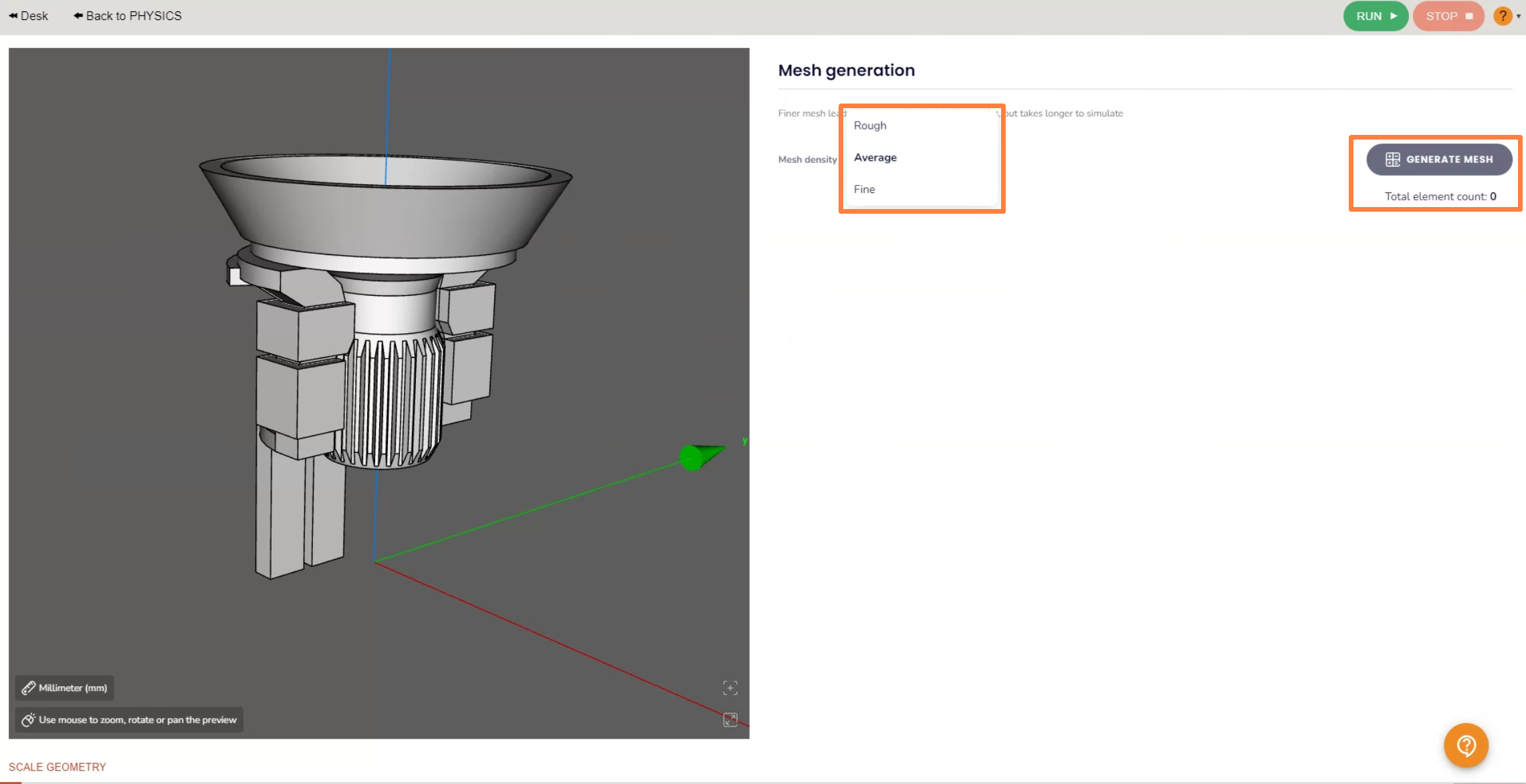
CENOS has an integrated mesh builder, after setting up the physics, click GO TO MESH to enter physics setup.
Select how dense you want the automatic mesh to be
In case you want to make any changes to the mesh generated by our algorithm you can do it by enabling the mesh refinement and selecting the element you'd like to adjust
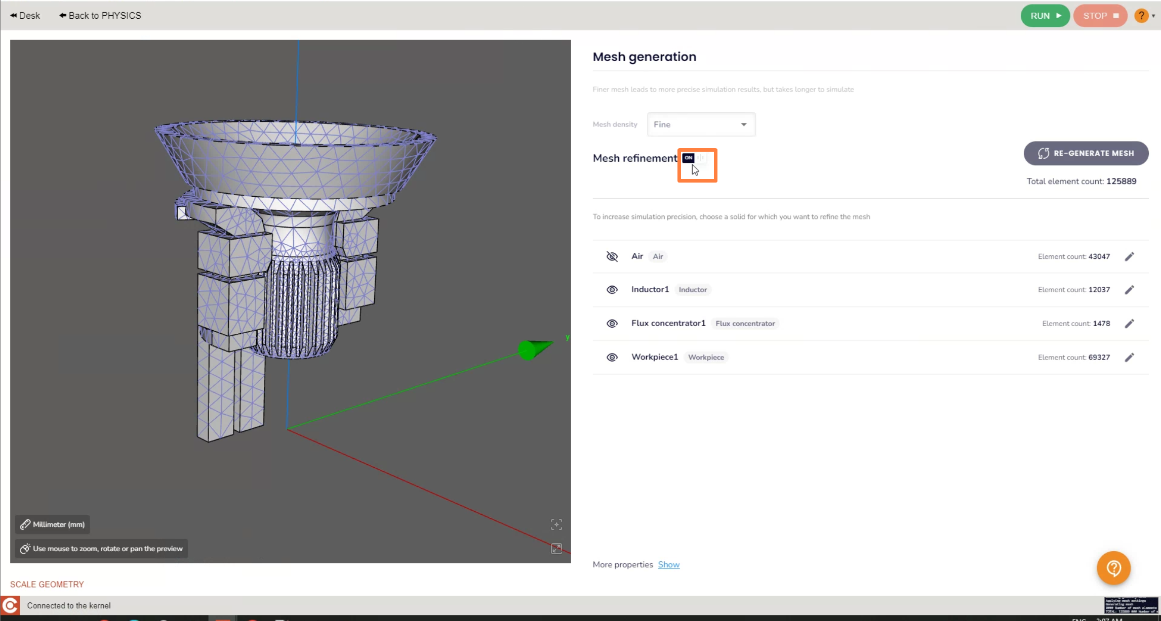
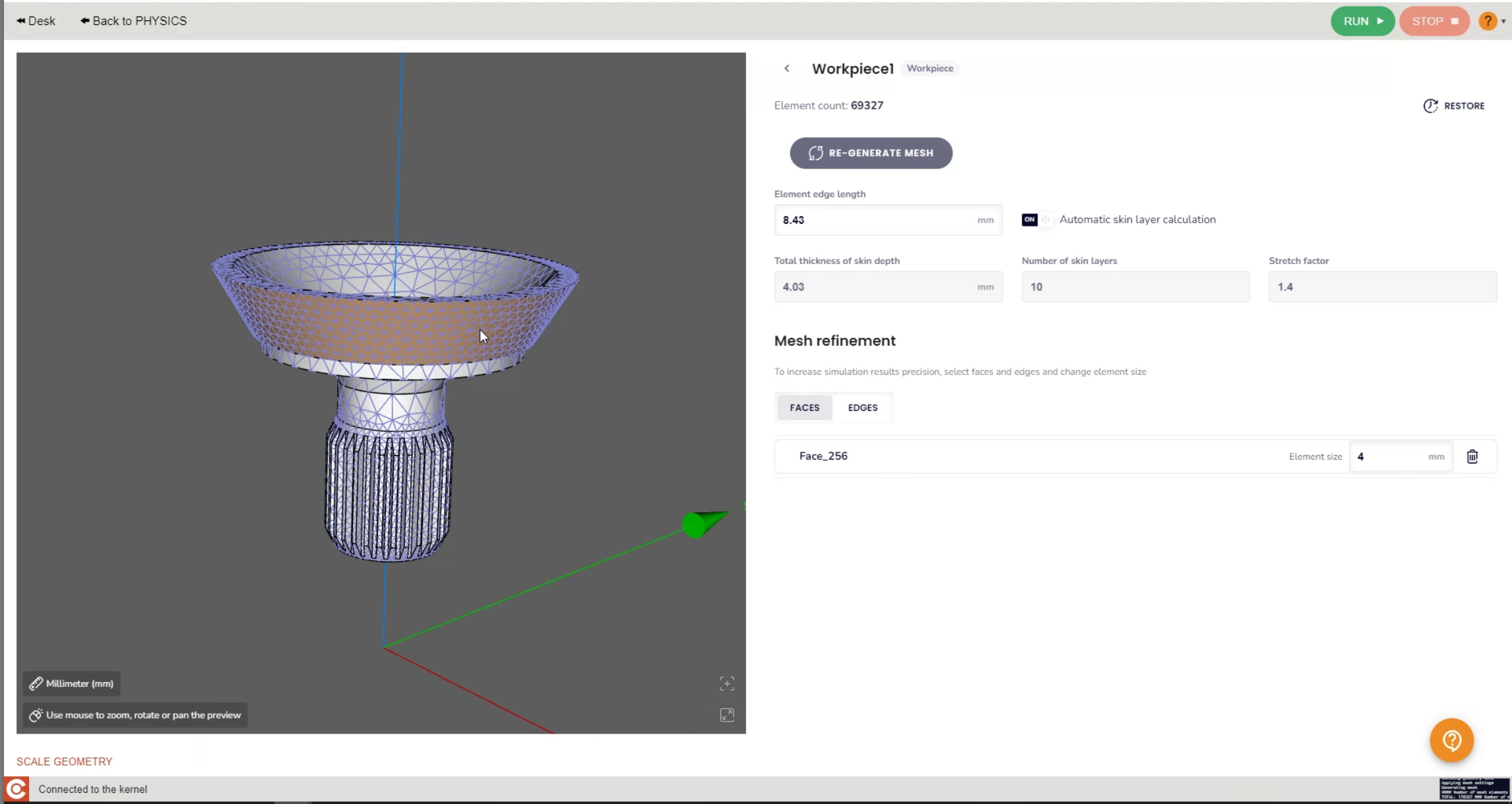
From there, you will be able to disable the automatic skin layer calculator and refine the whole section, or faces and edges, according to your needs.
To learn more about meshing, visit our meshing documentation.
Post-processing
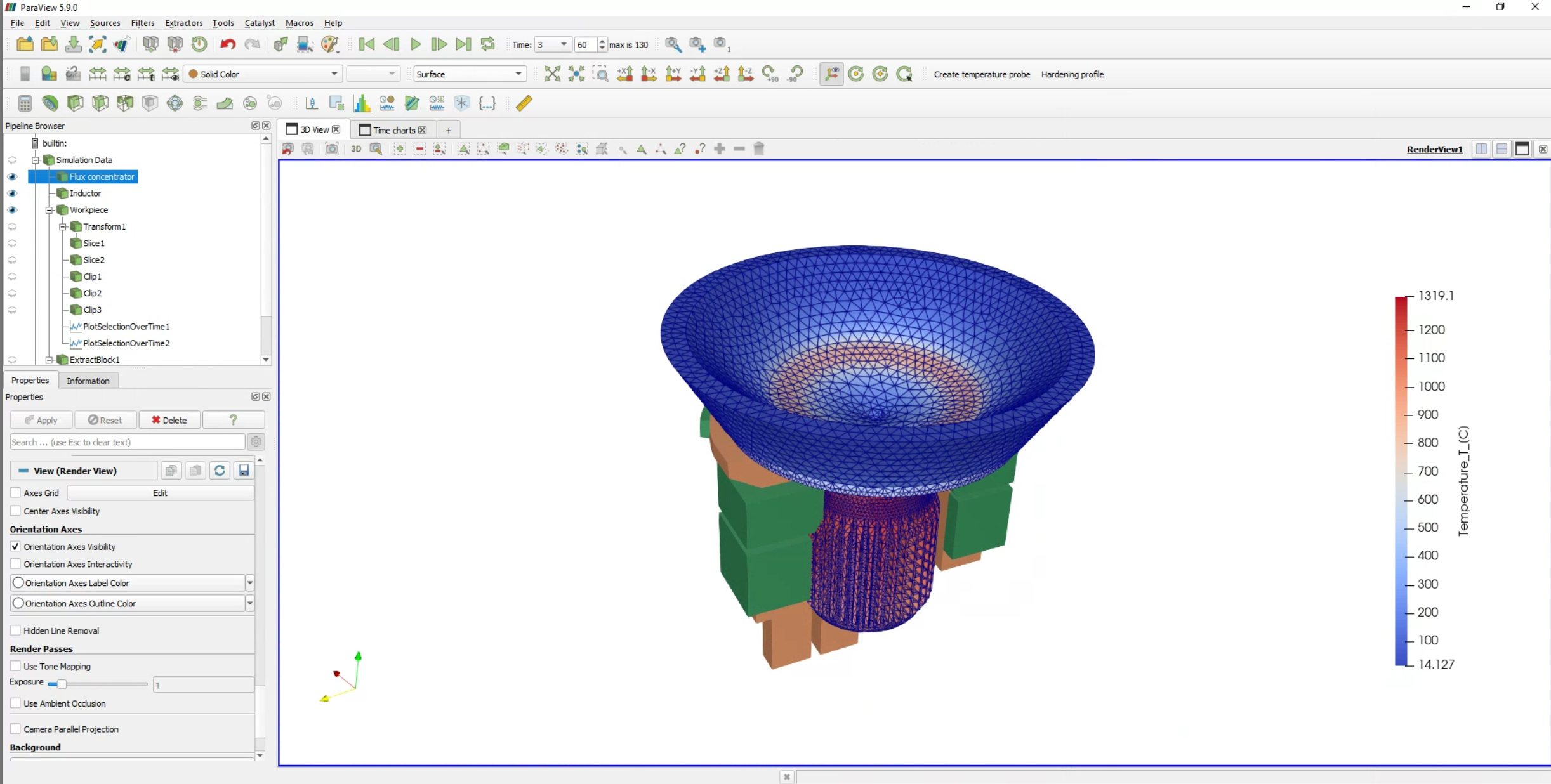
In the end of the calculation the post-processing tool ParaView will automatically open with a pre-set temperature state, and you will be able to see the temperature field distribution in the workpiece on the last time step.
To learn more about customizing the view of results, visit our result evaluation article.
Integral values
For integral values such as apparent power, induced heat and complex voltage you can use the .csv file, which is generated along with the visual results. You can access it through the Note button next to the Visualization block Play button.
